ObjectID
The stable identifier that follows the object through raw capture, processing, preservation, and access.
Hover a card for a quick scan, then click it to jump straight to that part of the page.
Use stable, descriptive names that include object identity, part identity (if needed), date, version, and file role. Hover or click each segment to see what it contributes.
The stable identifier that follows the object through raw capture, processing, preservation, and access.
Use this slot for a part code, assembly name, or capture/view description so users know what this file actually represents.
A machine-sortable date shows when the file version was created and helps distinguish milestones without relying on memory.
The version number marks a discrete saved state. Keep the numbering simple and sequential so later files sort in order.
This tells people the file role at a glance: raw capture, preservation master, access copy, print derivative, or another local stage you document.
The extension names the actual format and signals likely dependencies. It matters because one stage can exist in multiple formats with different preservation value.
CoopersHawk_001_wing_exterior_20260220_v01_raw.tif
CoopersHawk_001_master_assembly_20260224_v03_pres.obj
CoopersHawk_001_web_20260224_v01_access.glb
Keep names machine-sortable and avoid spaces or punctuation that can break scripts.
Open the example, then hover or click each file to see how the package works as one connected unit.
Example
Trace how geometry, materials, textures, scene notes, metadata, and paradata stay connected.
The thesis treats 3D data as a compound object. Below are the pieces that may need to travel together:
CoopersHawk_001_master_assembly_v03.obj holds the specimen's form. It is the core file, but it still depends on the rest of the package to represent the model completely.
CoopersHawk_001_feather_diffuse.png carries color and surface detail. If it gets separated from the mesh and material file, the model may open with the right shape but the wrong appearance.
CoopersHawk_001_master_assembly_v03.mtl tells software which textures belong on which surfaces and how the geometry should be rendered.
assembly_relationships.json records relationships that do not fit neatly inside the mesh itself, such as transforms, part arrangement, or other structural context needed for reuse.
CoopersHawk_001_Metadata.txt identifies the object, describes capture context, and documents which files belong together in the package.
CoopersHawk_001_paradata.txt explains the human decisions behind the model, such as filtering, registration, smoothing, decimation, and export choices.
CoopersHawk_001_preservation_package/
  geometry/CoopersHawk_001_master_assembly_v03.obj
  materials/CoopersHawk_001_master_assembly_v03.mtl
  textures/CoopersHawk_001_feather_diffuse.png
  metadata/object_metadata.txt
  metadata/paradata.txt
  assembly/assembly_relationships.json
Each preview below opens the full image in a new tab, and each card has its own direct page link for sharing.
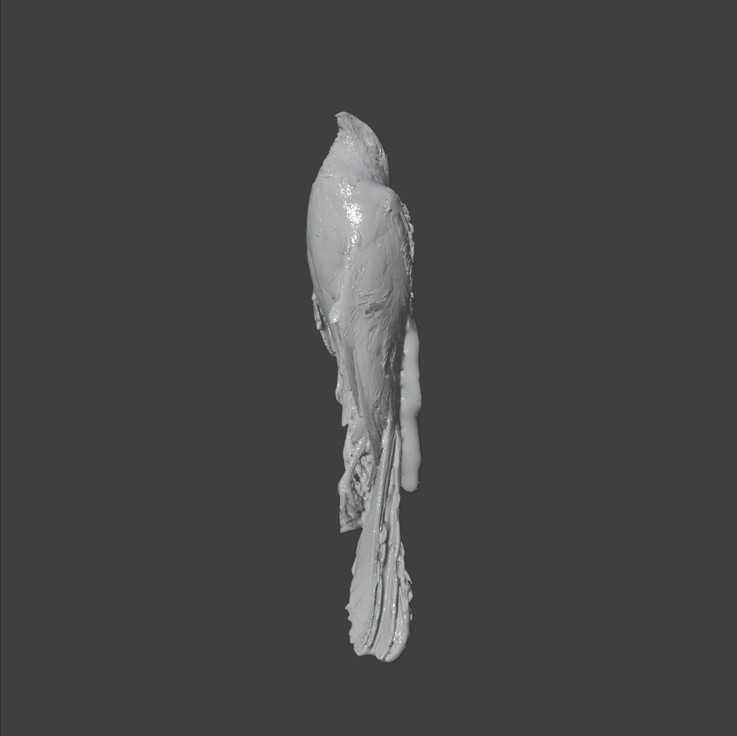
The mesh image shows the geometry structure the OBJ carries before texture and material interpretation are applied.
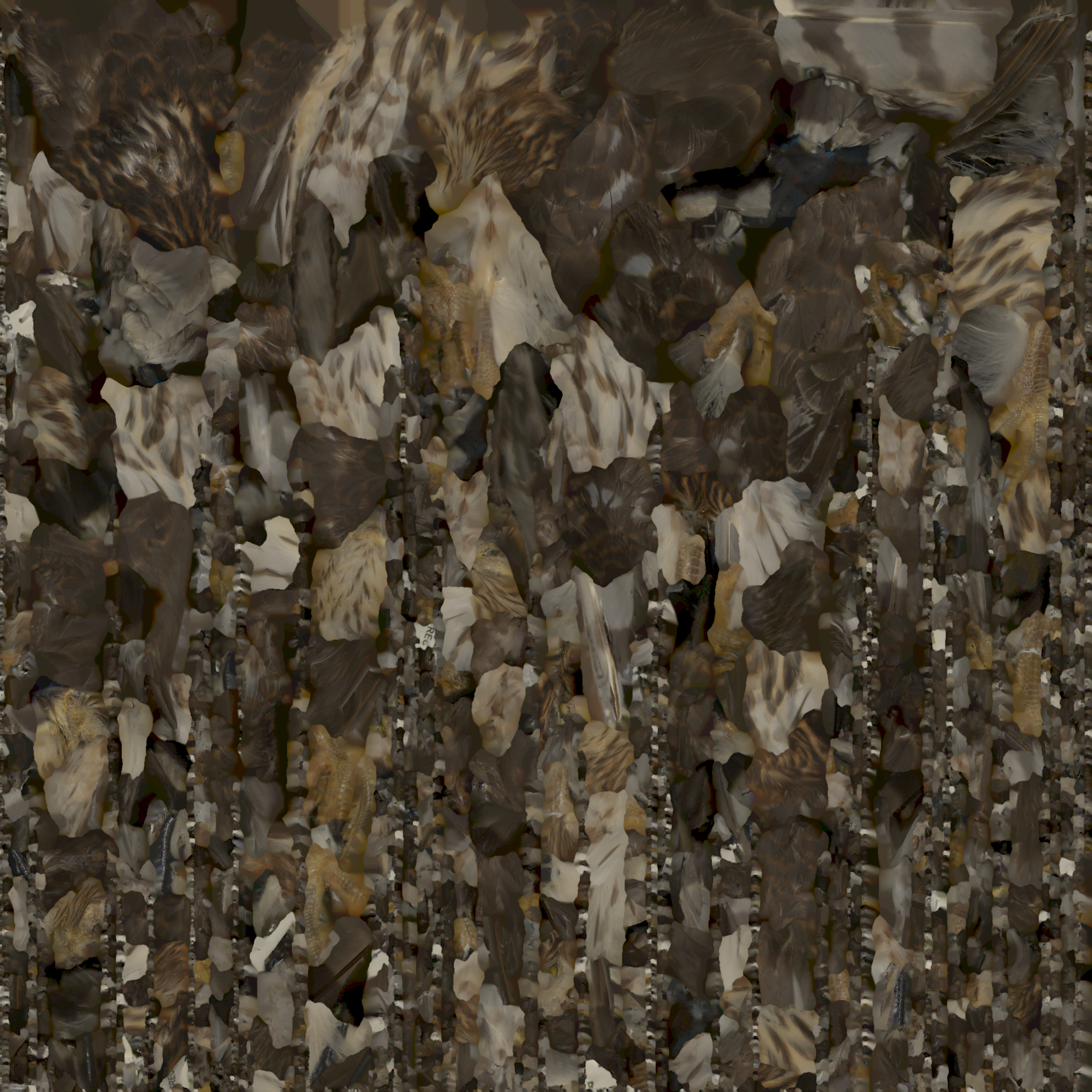
The texture image supplies the surface color data that the material file maps back onto the mesh.
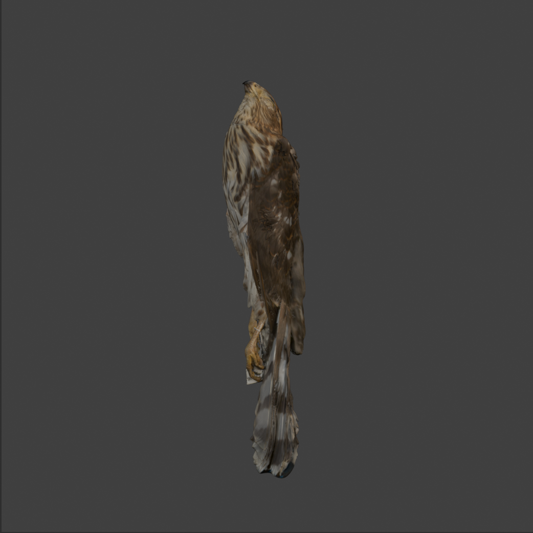
This rendered view represents the appearance produced when the material instructions successfully connect the mesh to its texture.
Long-term preservation depends on format qualities, not short-term popularity. Guidance from organizations such as the Library of Congress and Duke Libraries prioritizes formats that remain readable across tools and over time.
No single format covers every need. Use different formats for mesh fidelity, point-cloud preservation, access delivery, and print production.
Mesh formats
Open this when you need surface mesh tradeoffs for preservation and access.
| Format | Preservation pros | Preservation cons | Web/access pros | Web/access cons |
|---|---|---|---|---|
| OBJ (+MTL) | Open, documented, and broadly readable. | Materials/textures are sidecars and can be separated. | Easy to convert to GLB for viewers. | Not efficient to deliver directly in-browser. |
| PLY | Good geometry plus per-vertex color/attributes. | Limited material/scene semantics across tools. | Useful for research viewers after conversion. | Not a common direct web runtime format. |
| USD | Strong scene structure, composition, and variant support. | More complex pipeline and governance requirements. | Works well in advanced 3D ecosystems. | Inconsistent browser-native support compared to GLB. |
| glTF/GLB | Single-file GLB can simplify packaging for derivatives. | Typically optimized/compressed for delivery rather than full-fidelity masters. | Fast, lightweight, and widely supported in web viewers. | May drop high-detail data needed for long-term authority. |
Point cloud formats
Open this when you need scan-source formats rather than surface-mesh delivery formats.
| Format | Preservation pros | Preservation cons | Web/access pros | Web/access cons |
|---|---|---|---|---|
| E57 | Open and suited for LiDAR/scan retention with scan metadata. | Harder for non-specialist teams to inspect manually. | Reliable source for creating web-ready derivatives. | Rarely served directly in browser viewers. |
| XYZ | Simple, transparent coordinate export. | Minimal metadata/context unless documented separately. | Easy import path to processing tools. | Large plain-text files are heavy for web delivery. |
| LAS/LAZ | Standardized point-cloud schema with optional compression (LAZ). | Field consistency can vary by producer workflow. | Common input for tiled/streamed point-cloud services. | Often requires preprocessing before public viewing. |
3D printing formats
Open this when you need fabrication-focused formats and their preservation limits.
| Format | Preservation pros | Preservation cons | Web/access pros | Web/access cons |
|---|---|---|---|---|
| STL | Very widely supported for fabrication workflows. | Geometry only (no color, units, materials, or provenance). | Easy to preview after conversion in many tools. | Weak direct web accessibility and no rich context. |
| 3MF | Package can include units, materials, and print settings. | Preservation quality depends on slicer/vendor feature compatibility. | Better contextual print data than STL. | Not a standard browser delivery format. |
| AMF | Designed to represent richer print semantics than STL. | Lower real-world adoption and tool support. | Can preserve more manufacturing context when supported. | Limited interoperability for public access workflows. |
| G-code | Captures machine-ready print instructions for specific jobs. | Device/profile dependent and not a reusable master geometry format. | Useful for documenting print execution. | Not suitable as a general public 3D access format. |
Preservation and delivery have different goals. Keep a master-plus-derivative workflow and retain original scan data whenever possible.
In both comparison views below, the left model is the access copy at 10,000 faces and 5.65 MB, while the right model is the preservation model at 1,000,000 faces and 107 MB.
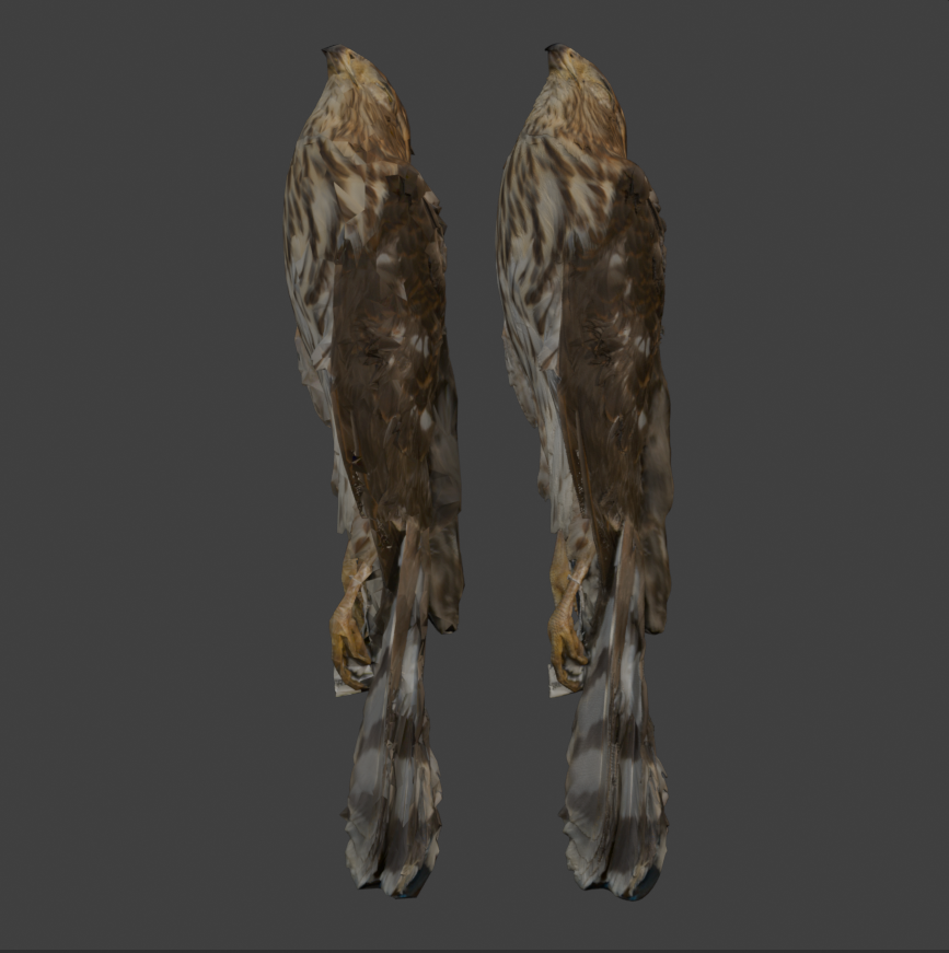
This view shows how an access derivative can stay visually useful while carrying far fewer faces than the preservation master.
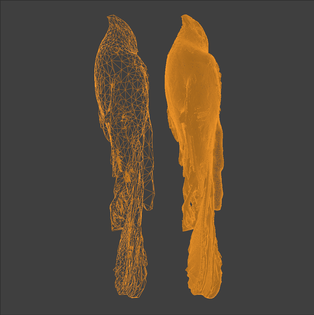
The wireframe view makes the reduction in mesh density explicit, which is useful when documenting how the access copy was derived.
Never invent a false authoritative name. Use a placeholder you can defend.
InsectSpecimen_045_unknown_wing_fragment
Machine_002_unknown_component_A
Machine_002_rotating_disc_component
Artifact_014_small_curved_metal_piece
UnknownObject_001
Unidentified_Component_003
Key rule: file names describe what you know. Metadata describes uncertainty.
You have two valid structural models, and for complex machines you will often use both:
Best when the machine itself is the long-term intellectual object you care about.
Best for documenting workflow context for one campaign, survey, or time-bounded initiative.
If the machine is scanned within a larger survey, keep both contexts:
Projects/
  FactorySurvey_2026/
    Machine_12_WaterPump/

Objects/
  Mechanical/
    WaterPump_001/
Do not collapse these into one folder tree. For complex machines, use project structure for workflow and object structure for durable identity.
Objects with parts
Open this when you need parent assemblies, child parts, and relationship files to stay legible together.
If the machine is the intellectual "thing" you care about long-term, keep it as a parent object with child parts.
Objects/
  Mechanical/
    WaterPump_001/
      assembly/
        WaterPump_001_master_assembly_v01.pres.obj
        assembly_metadata.txt
      parts/
        WP001_P01_Impeller/
        WP001_P02_Housing/
        WP001_P03_Shaft/
      documentation/
        metadata.txt
        paradata.txt
        rights_and_access.txt
Use a consistent part code:
WaterPump_001_P01_Impeller
WaterPump_001_P02_Housing
Pattern: [ParentID]_P[##]_[PartName]
Keeps every part visibly attached to its parent object so the relationship survives outside the folder tree.
A sequential code works well when physical or assembly order matters and helps machines sort parts correctly.
Use a human-readable label for quick recognition. Keep it descriptive enough that people can identify the component without opening the file.
File structure alone is not enough. You need structural hierarchy, assembly metadata, and relationship documentation.
assembly/
  WaterPump_001_master_assembly_v01.pres.obj
  assembly_relationships.json
{
  "parent_object": "WaterPump_001",
  "parts": [
    {
      "id": "WP001_P01_Impeller",
      "connects_to": "WP001_P03_Shaft",
      "connection_type": "rotational_fit",
      "alignment_reference": "central_axis"
    },
    {
      "id": "WP001_P02_Housing",
      "contains": "WP001_P01_Impeller",
      "connection_type": "enclosure"
    }
  ]
}
parent_object: WaterPump_001
part_number: P01
assembly_position: internal rotating component
fits_with: WP001_P03_Shaft
This creates bidirectional traceability between parent assembly records and child part records.